
2024年07月13日
So you’ve heard all about the cool open-source robot physics engine MuJoCo, you’ve tried out the sample robot models (e.g. in MuJoCo Menagerie), and now you want to simulate your own robot in MuJoCo- but how to do it? MuJoCo uses the MJCF XML format for its models, and also supports the URDF format. Although some converters from CAD models directly to URDF models exist, so far I’ve found it much easier to just write the MJCF model from scratch yourself. This lets you keep track of all the model parameters consistent since you write it yourself, and it’s not as complicated as you may think. So in this article I’ll explain the easiest method that I know so far to manually convert your robot model in CAD to a simulated version in MuJoCo! And at the end, I’ll also show you how to get the MJCF model to also work in IsaacGym.
click here for the Japanese version
If you want to implement more advanced features not covered here, reading through these example models could help you:
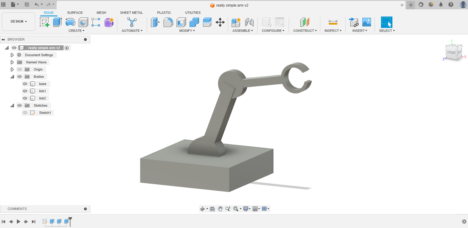
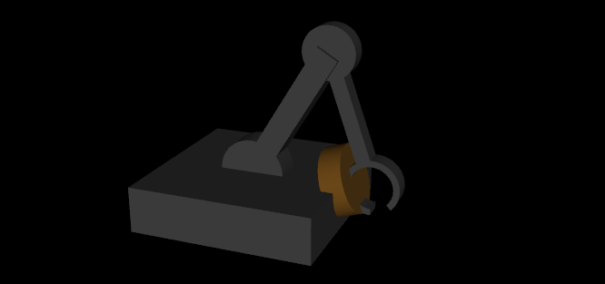
It doesn’t matter if the model is articulated with joints or not, since that will have to be defined separately in the MJCF file anyway later. Here, as an example I made a really simple robot arm model with two joints in Fusion 360.
If you want, you can access this CAD design in the Fusion online hub or get the .step file here. This model doesn’t have to be articulated, but at least make sure that each link is a separate body, so that the meshes can be exported separately. And you can get the files for the final MJCF model from this Google Drive folder or from this zip file.
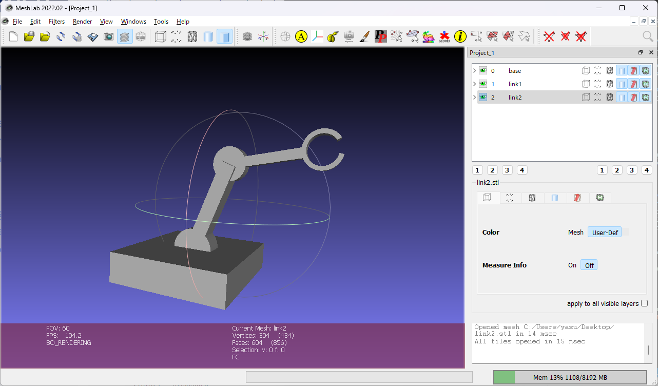
Export each link in the CAD as a separate STL file (OBJ and MSH file types are also supported). Here, I’ve found the key to making this conversion process easy is to ensure that all the meshes are saved in the same global frame. It depends on which CAD software you use, but at least for Fusion 360, you can ensure this by:
If you want to be really sure that the meshes are in the same frame, you could load all of them into a mesh editor program (e.g. MeshLab) and check that they do come together into an assembled robot as intended.
Here, the official documentation is your friend. Although it is long, it should have every single information you need, and you should keep coming back to it any time you’re stuck. https://mujoco.readthedocs.io/en/latest/XMLreference.html
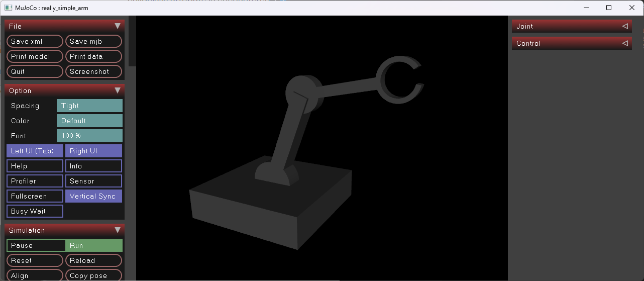
Another friend is the simulate binary program that comes with your mujoco installation. (If you installed mujoco with pip, you can launch it with python -m mujoco.viewer) Drag and drop the model file into it, and it will load it (or, tell you if there is an error within the model). While you’re writing the XML file, make sure to load it often into this simulator for a sanity check!
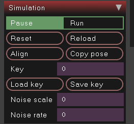
This simulate program has many options in the sidebar, which you should fully take advantage of- for example, here you can Pause / Run the simulation (can also be toggled with the space bar), Reset it to its original state, or Reload the XML file (if you updated its contents).
 The other panels also are useful too, like visualizing actuator positions or contact forces, and even changing the physics parameters like gravity. I recommend you spend some time exploring all of its tools- it should help a lot with debugging the model.
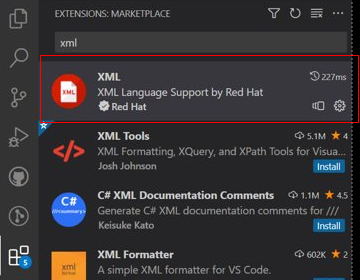
Also, if you’re new to writing XML, you should use tools to help you make sure that all tags are properly closed and properly indented. If you’re using VSCode, install XML extension, and in the editor, press ctrl-shift-p to open commands, and “format with” → “XML” to apply automatic indentation.
Ok, now let’s first add the meshes to the file. Create a file my_robot.xml, and copy the mesh files to the same directory.
<mujoco model="really_simple_arm">
    <default>
        <!-- convert the Fusion 360 coordinate system to MuJoCo -->
        <geom type="mesh" xyaxes="1 0 0 0 0 1"/>
    </default>
    <asset>
        <!-- Fusion outputs meshes with mm units by default, but must be converted to m in MuJoCo, hence the scaling -->
        <mesh name="base" file="base.stl" scale="0.001 0.001 0.001"/>
        <mesh name="link1" file="link1.stl" scale="0.001 0.001 0.001"/>
        <mesh name="link2" file="link2.stl" scale="0.001 0.001 0.001"/>
    </asset>
    <worldbody>
        <body name="base">
            <geom mesh="base"/>
            <body name="link1">
                <geom mesh="link1"/>
                <body name="link2">
                    <geom mesh="link2"/>
                </body>
            </body>
        </body>
    </worldbody>
</mujoco>
If you load this in MuJoCo, it already shows the robot!
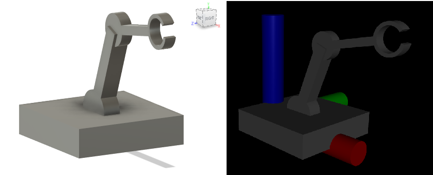
you may wonder what the line <geom type="mesh" xyaxes="1 0 0 0 0 1"/> within the <default> element is doing- it is setting the default attributes for the geom element, which will be used unless overridden in each <geom> instance within the bodies. MuJoCo uses a coordinate system that is conventional for robots, where the x axis points forward and the z axis points up - which is different from the CAD software’s axes, so the rotational transformation xyaxes="1 0 0 0 0 1" is needed. On the left you can see the CAD’s axes and on the right you can see MuJoCo’s (the RGB colors respectively corresponds to XYZ axes)
Measure each joint’s xyz position in the CAD software, and add the joint under each <body> tag.
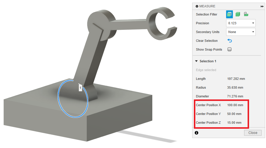
for example, this first joint can be defined by adding this under <body name="link1"> in the XML file (again, be careful about the different order of the axes):
<joint name="joint_1" pos="0.1 -0.015 0.05" axis="0 1 0" limited="true" range="-45 45"/>
The second joint can be added by adding this after the <body name="link2"> element:
<joint name="joint_2" pos="0.1583 -0.01 0.1994" axis="0 1 0" limited="true" range="-90 90"/>
If you pause the simulation, then you can control each joint angle in the right panel.
At this point, (if your initial CAD model was messily designed like mine and if it has internal interferences) there may be a large collision force being generated between each body. This can be visualized with by enabling the “Contact Point” / “Contact Force” in the “Rendering” tab (As I mentioned,these tools are useful!).
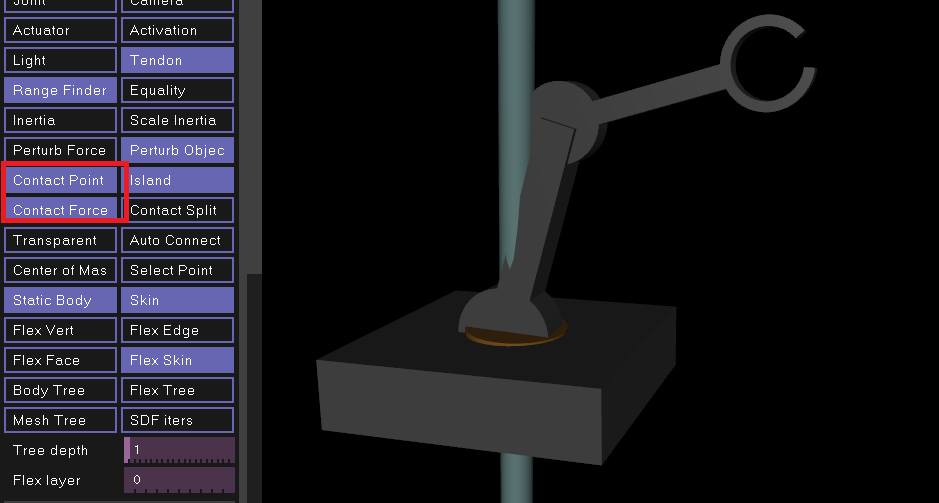
We can come back to this later- for now, all contacts can be disabled by selecting “Contact” under Physics → Disable Flags in the simulate GUI. (This can also be always disabled if you set <flag contact="disable"> in the option in the XML)
Next let’s define actuators for each joint. There are several different types of actuators available in MJCF, but we can use the position actuator, which basically applies PD control to the joints. Add this below <worldbody>:
    <actuator>
        <position name="joint_1" joint="joint_1" ctrllimited="true" ctrlrange="-0.78 0.78" kp="1" kv="0.1"/>
        <position name="joint_2" joint="joint_2" ctrllimited="true" ctrlrange="-1.57 1.57" kp="1" kv="0.1"/>
    </actuator>
Now, the XML can be written like this (note that I set some defaults to clean up the XML):
<mujoco model="really_simple_arm">
    <compiler angle="radian"/>  <!-- use radians to define angles -->
    <option>
        <!-- Note: if using mujoco version earlier than 3, set <option collision="predefined"/> instead -->
        <flag contact="disable"/>
    </option>
    <default>
        <!-- set default attributes to clean up XML -->
        <!-- convert the Fusion 360 coordinate system to MuJoCo by setting a transform with xyaxes-->
        <geom type="mesh" xyaxes="1 0 0 0 0 1"/>
        <joint type="hinge" limited="true" axis="0 1 0"/>
        <!-- kp is proportional gain, kv is damping gain -->
        <position ctrllimited="true" kp="1" kv="0.1"/>
    </default>
    <asset>
        <!-- Fusion outputs meshes with mm units by default, but must be converted to m in MuJoCo, hence the scaling -->
        <mesh name="base" file="base.stl" scale="0.001 0.001 0.001"/>
        <mesh name="link1" file="link1.stl" scale="0.001 0.001 0.001"/>
        <mesh name="link2" file="link2.stl" scale="0.001 0.001 0.001"/>
    </asset>
    <worldbody>
        <body name="base">
            <geom mesh="base"/>
            <body name="link1">
                <joint name="joint_1" pos="0.1 -0.015 0.05" range="-0.78 0.78"/>
                <geom mesh="link1"/>
                <body name="link2">
                    <joint name="joint_2" pos="0.1583 -0.01 0.1994" range="-1.57 1.57"/>
                    <geom mesh="link2"/>
                </body>
            </body>
        </body>
    </worldbody>

    <actuator>
        <position name="joint_1" joint="joint_1" ctrlrange="-0.78 0.78"/>
        <position name="joint_2" joint="joint_2" ctrlrange="-1.57 1.57"/>
    </actuator>
</mujoco>
I showed a way to just disable all contact in case there is internal interferences, but that obviously is not the optimal solution- one way to still simulate contact while avoiding these internal forces, is to set up contact exclusion pairs between neighboring bodies. By setting this up, the <flag contact="disable"/> element can be deleted, and now, the collision is properly calculated between link2 and the base when they bump against each other!
<contact>
    <exclude body1="base" body2="link1"/>
    <exclude body1="link1" body2="link2"/>
</contact>
There are many elements you would have to adjust to make the simulation behave the same way as a real robot- way too many to cover in this post (it’s basically a research field of its own). For example, the joint damping and actuator gains could be tuned so that the actuation response matches that of the real robot.
For now, let’s just check the mass.
By default, the mass will be automatically calculated for each <geom> from the mesh shape, assuming density of water.
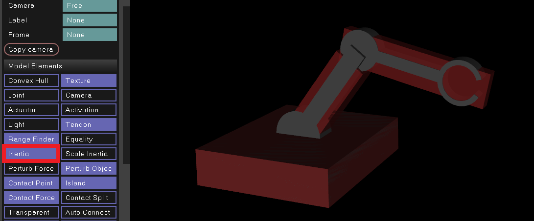
I recommend setting the mass in the <geom> to the actual measured mass, if you have a physical robot in real life - then, the rotational moment of inertia will automatically be calculated based on the geom’s shape.
https://mujoco.readthedocs.io/en/latest/XMLreference.html#body-geom
Visualizing the inertia will show the inertia box, helping you verify the mass settings.
Again, note that you can get all the files for the final MJCF model, including STLs, from this Google Drive folder or from this zip file.
I know that some people want to simulate their robot in IsaacGym, so they can train it with reinforcement learning. IsaacGym does support MJCF. However, this is a whole another rabbit hole, since their implementation for the MJCF parser is kind of half-baked and not all models that work in MuJoCo will work in IsaacGym. And most of the time, it will not tell you if you using an unsupported feature!
You can get a peek at some of the user reported issues from the forum: https://forums.developer.nvidia.com/search?q=MJCF
I can’t write all of them here, but here are some things that we found won’t work in IsaacGym:
xyaxes, are not supportedkv attribute doesn’t exist in the position actuator pre-3.0, so you will have to set the damping in the joint element instead.For me I had to spend some time struggling to find out what exactly was causing my robot to not show up in IsaacGym. I recommend looking at the MJCF models that already do work in IsaacGym (like the ones that I showed at the beginning of this post) and using just the elements found in those models.
So if you want to use the model that we built in this post in IsaacGym, you’ll have to change the xyaxes="1 0 0 0 0 1" that defines the geom default orientation to use quaternions instead (I originally used xyaxes in the tutorial since it’s more intuitive). So just change that to quat="0.7071068 0.7071068 0 0" and the same structure will be loadable.
I’ve found this 3D Rotation Converter website to be very useful for calculating such conversions, but be careful that MuJoCo’s quaternions are in w x y z order, not the x y z w order shown in the converter.
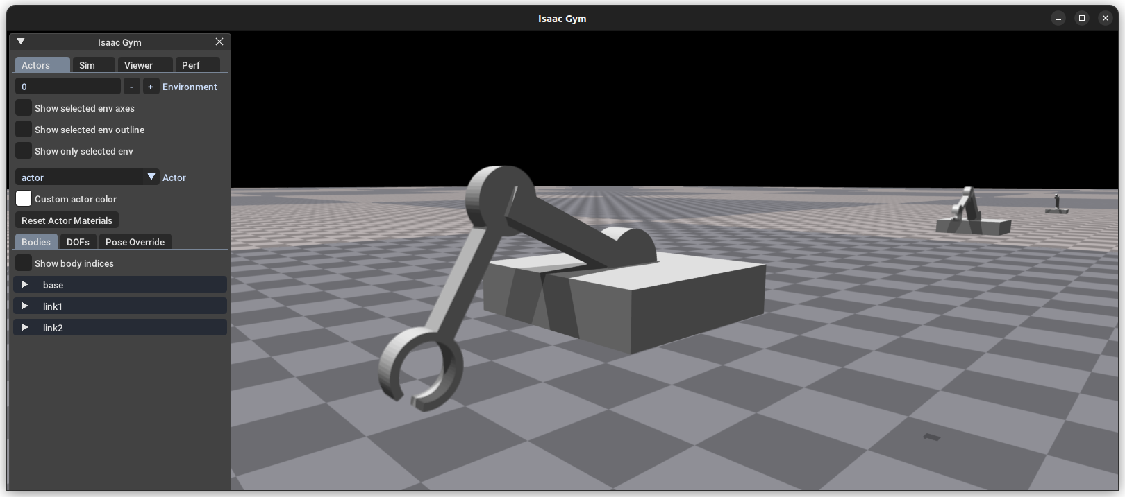
If you want to quickly view your robot in IsaacGym, you can add your robot to one of their sample programs (e.g. actor_scaling.py) and see that the robot is loaded correctly:
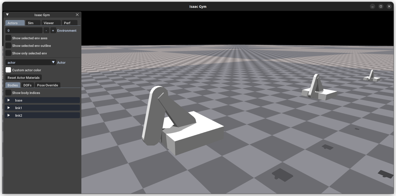 However, you will see that only the convex hull of the mesh is shown - that is the convex hull used for IsaacGym’s contact calculations. If you want to see the actual mesh, you can follow the example of the Shadow Hand model in IsaacGymEnvs to create two classes of geoms- one for collision and one for visualization. I’ve included
 my_robot_isaacgym.xml in the sample model directory with these changes already applied, so you can quickly try it out yourself.
By the way, if you set asset_options.vhacd_enabled = True, convex decomposition will be automatically applied to the collison mesh, so that you can simulate the robot even if the shape is somewhat nonconvex (I only found out about this “secret” option very recently- I wish it were more clearly introduced!).
You can check out what we’ve worked on last year using IsaacGym and our own robot hand, in the “Get the Ball Rolling” project website. And if you’re interested in using our framework to train a RL policy for your hand, you can check out this tutorial video that I created as part of the Real World Robotics class at ETH Zurich:
The methods I introduced here will help you make a first model that at least has the correct kinematics, but of course there are so many other elements to improve the verisimilitude of your simulation - friction, damping, actuator parameters, etc. Even once the basic model starts working, you will have to keep reviewing and adjusting your model to improve it. But I hope that this post can help you take the first step into this world of robot simulators!
□
Simulating YOUR robot in MuJoCo - how to create a MJCF file from a CAD model
 【2/2】 Setting up a VPN server on Windows and connecting from iPhone without changing router settings: Client Settings & Setup & Management Tips
 【1/2】Setting up a VPN Server on Windows and Connecting from iPhone without Changing Router Settings: Overview & Server Settings